- Laminated Busbar
- Film Capacitor
- Film Capacitor for HEV / EV Motor Control Unit
- DC-Link Capacitor ( Dry-Type, Plastic Case, Maximum Temperature 85℃)
- DC-Link Capacitor ( Dry-Type, Plastic Case, Maximum Temperature 105℃)
- MKP DC-Link Film Capacitor
- Water Cooled Heat Sink
- Flat Heat Pipe
- Reactor
- Water Cooling Reactor
- Input AC Reactor
- Output AC Reactor
- DC Reactor
- Reactor for Explosion-Proof Inverter
- Sine Wave Filter
- Detuned Reactor
- DV/DT Filters
- Three-Phase Input Filter
- Resistor
- Wirewound Resistor
- Aluminum Enclosure Resistor
- Aluminum Housed Resistor
- Die-Casting Aluminum Resistor
- Aluminium Resistor (Multiple Unit)
- Thick Film Resistor
- Braking Resistor Box
- Wirewound Tubular Fixed Resistor
- Power Resistor Unit
- Crowbar Resistor
- Braking Unit
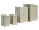
Three-phase Input Filter
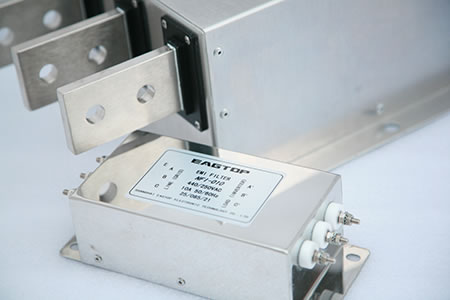

Construction
3-phase, 3-wire filter
Metal case
Various terminal connection configurations
Features
1. High insertion loss
2. Excellent EMI noise suppression
3. Optimized for long motor cable and operation under full load
4. Guaranteed compliance with EN 55011/IEC 61800-3
5. Design complies with IEC 60939, UL 1283, CSA 22.2 No.8
Inverters and Frequency Converters Applications
Elevators, cranes, traction system
HVAC systems (heating, ventilation and air conditioning)
General three phase motor drive systems
Machine tools: printing machine, packaging machine, milling and drilling machine,
Textile machine
Three-phase power supplies and UPS
| Rated voltage(VR) | 440VAC, 50/60Hz |
| Rated current(IR) | 5 ~ 1200A @ 40 °C |
| Test voltage(VP) | 2250VDC, 5S(Line to line) 2550VDC, 5S(Line to case) |
| Temperature range (operation and storage) | -25 °C /+85 °C (25/085/21 IEC 60068 − 1) |
| Overload capability (thermal) | 1.5 x IR 3min/hour 2.5 x IR 30s/hour |
| Filter type | Rated current @40°C [A] | Typical drive power rating[KW] | Leakage current @400VAC/50Hz [mA] | Rtyp[mΩ] | Input/Output connections | Dimensions | Weight | ||
| NFI-0005-SA | 5 | 0.75 ~ 1.5 | < 6 | 18 | √ | Picture A | 0.8 | ||
| NFI-0010-SA | 10 | 2.2 ~ 4 | < 6 | 7 | √ | Picture B | 1.5 | ||
| NFI-0020-SA | 20 | 5.5 ~ 7.5 | < 6 | 7.4 | √ | Picture C | 2.8 | ||
| NFI-0036-SA | 36 | 11 ~ 15 | < 6 | 3.7 | √ | Picture C | 3 | ||
| NFI-0050-SA | 50 | 18.5 ~ 22 | < 6 | 2.1 | √ | Picture C | 3.1 | ||
| NFI-0065-SA | 65 | 30 | < 10 | 1.9 | √ | Picture D | 5 | ||
| NFI-0080-SA | 80 | 37 | < 10 | 2.3 | √ | Picture E | 7.2 | ||
| NFI-0100-SA | 100 | 45 | < 10 | 2.1 | √ | Picture E | 7 | ||
| NFI-0150-SA | 150 | 55 ~ 75 | < 10 | 1.9 | √ | Picture E | 7.7 | ||
| NFI-0200-SA | 200 | 90 | < 30 | 0.4 | √ | Picture F | 5.5 | ||
| NFI-0250-BA | 250 | 110 ~ 132 | < 30 | 0.22 | √ | Picture G | 6.9 | ||
| NFI-0300-BA | 300 | 160 | < 30 | 0.21 | √ | Picture G | 6.9 | ||
| NFI-0400-BA | 400 | 200 | < 30 | 0.1 | √ | Picture H | 12 | ||
| NFI-0600-BA | 600 | 215 ~ 315 | < 30 | 0.13 | √ | Picture H | 12.4 | ||
| NFI-0900-BA | 900 | 400 | < 30 | 0.19 | √ | Picture I | 21.5 | ||
| NFI-1200-BA | 1200 | 630 | < 30 | 0.12 | √ | Picture I | 21.7 | ||
Note: If the leakage current of the filter is greater than 0.5mA, the product should not be used unless there is reliable grounding connection and protective measures. Otherwise, the risk of electric shock exists.
Electrical Diagram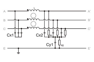 NFI-0005-SA~NFI-0036-SA
 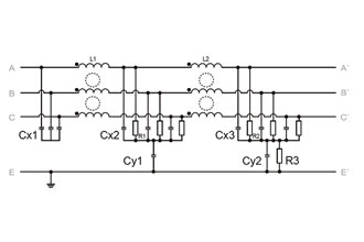 NFI-0050-SA~NFI-1200-BA
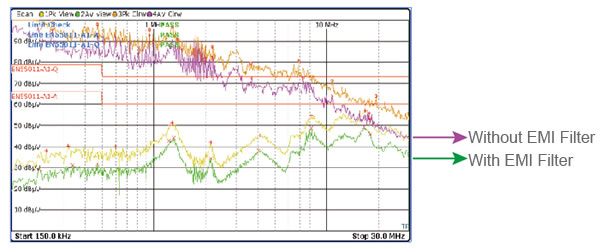
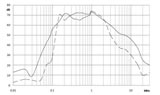
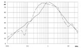
| Hz (MHz) | 0.15 | 0.5 | 1 | 5 | 10 | 30 |
| Input side noise level without EMI Filters(AV/dBμV) | 92 | 84 | 80 | 66 | 61 | 44 |
| Input side noise level with EMI Filters(AV/dBμV) | 20 | 25 | 34 | 32 | 40 | 36 |
| Noise damping factor due to EMI Filter application | 3981-fold | 891-fold | 199-fold | 50-fold | 11-fold | 2.5-fold |
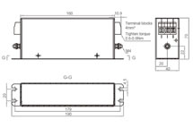
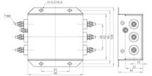 Picture A
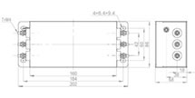 Picture B
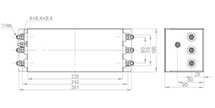 Picture C
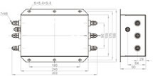 Picture D
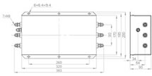 Picture E
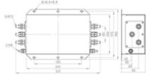 Picture F
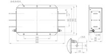 Picture G
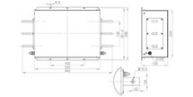 Picture H
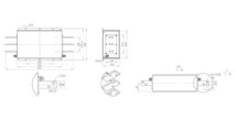 Picture I
 NFI-0005-SA
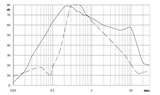 NFI-0010-SA
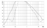 NFI-0020-SA
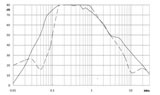 NFI-0036-SA
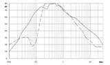 NFI-0050-SA
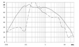 NFI-0065-SA
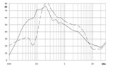 NFI-0080-SA
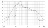 NFI-0100-SA
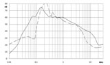 NFI-0150-BA
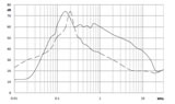 NFI-0200-BA
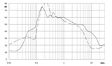 NFI-0250-BA
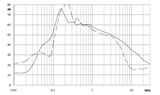 NFI-0300-BA
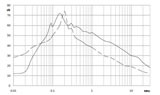 NFI-0400-BA
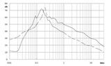 NFI-0600-BA
 NFI-0900-BA
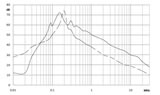 NFI-1200-BA
- common mode
- differential mode
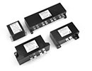
Construction
Three-phase, 3-wire filter
Metal case
Solid and safe connector blocks
Book style design
Product Features
1. Compact book style design and low weight
2. High insertion loss
3. Excellent EMI noise suppression
4. Degree of protection IP20
5. Ensured compliance with EN 55011/IEC 61800-3
6. Design complies with IEC 60939, UL 1283, CSA 22.2 No.8
Applications
3-phase variable speed motor drives, servo drives, inverters and converters machines or process automation equipment
HVAC equipment, elevators, power supplies, UPS
Machine tools: printing machine, packaging machine, milling and drilling machine, textile machine and so on.
| Rated voltage(VR) | 480VAC, 50/60Hz |
| Rated current(IR) | 7 ~ 150A @ 40 °C |
| Dielectric breakdown voltage(VP) | 2250VDC, 5S(Line to line) 2550VDC, 5S(Line to case) |
| Temperature range(operation and storage) | -25 ° C /+100 °C (25/100/21 IEC 60068 − 1) |
| Overload capability (thermal) | 1.5 x IR 3min/hour 2.5 x IR 30s/hour |
| Filter type | Rated current@40 °C [A] |
Typical VFD power rating[KW] |
Leakage current @400VAC/50Hz [mA] |
Rtyp[mΩ] | Input/Output connections | Dimensions |
Weight | ||
| NFI-0007-TB | 7 | 4 | < 5 | 9 | √ | Picture A | 0.9 | ||
| NFI-0016-TB | 16 | 7.5 | < 5 | 7 | √ | Picture B | 1.2 | ||
| NFI-0030-TB | 30 | 15 | < 5 | 5 | √ | Picture C | 1.6 | ||
| NFI-0042-TB | 42 | 18.5 | < 5 | 3.2 | √ | Picture C | 1.6 | ||
| NFI-0050-TB | 50 | 22 | < 5 | 2.1 | √ | Picture D | 3.1 | ||
| NFI-0065-TB | 65 | 30 | < 5 | 1.9 | √ | Picture D | 3.1 | ||
| NFI-0080-TB | 80 | 37 | < 10 | 2.3 | √ | Picture E | 6 | ||
| NFI-0110-TB | 110 | 45 | < 10 | 2 | √ | Picture E | 6 | ||
| NFI-0150-TB | 150 | 55~75 | < 10 | 1.8 | √ | Picture E | 6 | ||
Note: If the leakage current of the filter is greater than 0.5mA, the product should not be used unless there is reliable grounding connection and protective measures. Otherwise, the risk of electric shock exists.
Electrical Diagram- NFI-0007-TB~NFI-0042-TB
- NFI-0050-TB~NFI-0150-TB
| Frequency (MHz) | 0.15 | 0.5 | 1 | 5 | 10 | 30 |
| Input side noise level without EMI Filter (AV/dBμV) | 92 | 84 | 80 | 66 | 61 | 44 |
| Input side noise level with EMI Filters(AV/dBμV) | 20 | 25 | 34 | 32 | 40 | 36 |
| Noise damping factor due to EMI Filter application | 3981-fold | 891-fold | 199-fold | 50-fold | 11-fold | 2.5-fold |
 Picture A
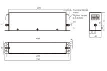 Picture B
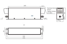 Picture C
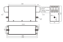 Picture D
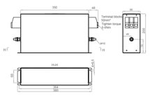 Picture E
 NFI-0007-TB
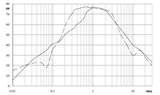 NFI-0016-TB
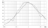 NFI-0030-TB
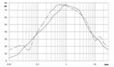 NFI-0043-TB
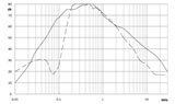 NFI-0050-TB
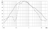 NFI-0065-TB
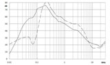 NFI-0080-TB
 NFI-0150-TB
- common mode
- differential mode