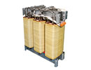
- Laminated Busbar
- Film Capacitor
- Film Capacitor for HEV / EV Motor Control Unit
- DC-Link Capacitor ( Dry-Type, Plastic Case, Maximum Temperature 85℃)
- DC-Link Capacitor ( Dry-Type, Plastic Case, Maximum Temperature 105℃)
- MKP DC-Link Film Capacitor
- Water Cooled Heat Sink
- Flat Heat Pipe
- Reactor
- Water Cooling Reactor
- Input AC Reactor
- Output AC Reactor
- DC Reactor
- Reactor for Explosion-Proof Inverter
- Sine Wave Filter
- Detuned Reactor
- DV/DT Filters
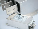
- Three-Phase Input Filter
- Resistor
- Wirewound Resistor
- Aluminum Enclosure Resistor
- Aluminum Housed Resistor
- Die-Casting Aluminum Resistor
- Aluminium Resistor (Multiple Unit)
- Thick Film Resistor
- Braking Resistor Box
- Wirewound Tubular Fixed Resistor
- Power Resistor Unit
- Crowbar Resistor
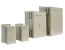
- Braking Unit
Composite Superconducting Flat Heat Pipe

The flat heat pipe is a heat transfer element with outstanding thermal conductivity. Replying on the special working fluid for heat and mass transfer during phase transition, the heat transfer device offers the thermal conductivity 10,000 times that of the heat tube produced from the same metal material. Apart from that, the flat heat pipe has the heat transfer capacity and pressure bearing capacity 5-20 times and 10-20 times that of traditional round heat pipe, respectively, whereas the cost of our product is less than 1/3 the cost of the traditional heat pipe.
Technical Parameters| Size (L×W×H) | (100~2000)*(10~180)*(1.2~8.0) mm |
| Heat Transfer Performance | 20W-200W |
| Temperature Difference | Temperature difference between the cooling end and heating end ΔT < 3℃ |
| Working Temperature | -60℃-120℃ |
| Max. Working Pressure | 0.6MPa-2.5MPa |
| Thermal Resistance | <0.05℃/W |
| Flatness | <0.05 |
| Cooling Mode | Free convection, forced convection, etc. |
| Surface Treatment | Natural color, nickel plating, anodic oxidation, chrome plating, and blackening. |
| Clean Energy | PV inverter heatsink, high-power LED heat dissipation module, ocean thermal energy conversion, heat transfer assembly. |
| Communication | Cooling components for power module |
| Computer, Communication, and Consumer Electronics | CPU, GPU heat dissipation module, LED backlight cooling component |
| Energy Conservation and Emission Reduction | Eco-friendly floor heating system, heating radiators, etc. |
| Efficient Heat Exchange System | Heat exchange system for air condition |
| Others | Industrial frequency converter, signal processing unit, UPS, medical appliance, laser, etc. |
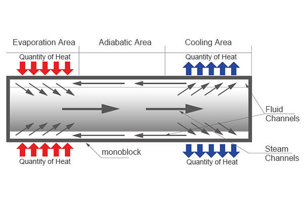
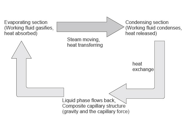
The working principle of FHP is shown in the Figurer 3, and its design is a typical one consisting of the sealed porous micro-capillary groove-array tube, working fluid and the composite capillary structure. After the tube is evacuated to the negative pressure of 1 x (10-2 ~ 10-3) Pa, it is filled with appropriate amount of working fluid and sealed. One end of the cavity is the evaporating section (heating section) and the other is the condensing section (cooling section). The evaporating section heated and the liquid evaporating, a slight differential pressure forces the steam to flow to the other end of the section. The heat released, it condenses into liquid and then flows back to the evaporating section in the direction of the gravity and the capillary force. So the constant loop goes and the heat transfers from one end of the pipe to the other.
SHANGHAI EAGTOP 3D Composite Superconducting Flat Heat Pipe Module (Third Generation)
1. The base plate (substrate) and composite superconducting flat heat pipe (FHP) constitute the 3D connected phase change heat transfer system.
2. When the phase change substrate is heated, the working medium absorbs heat and then is phased into steam, through which heat is transferred to each heat pipe (FHP) along the channels and simultaneously to the far ends.
3. The FHP dissipating fins exchange and release the heat, after which the working medium condenses and flows back to the substrate, ending the heat circulation.
Features
1. Due to the phase change technology used in the substrate which contacts the heat source area, the contact thermal resistance can be effectively controlled and reduced;
2. At the same time, the base plate and each heat pipe (FHP) constitute 3D working fluid phase change and transmission channels, thus effectively reduce the thermal resistance from the contact area (substrate) of the heat source to heat pipe (FHP), and improve the heat exchange efficiency of the heat pipes (FHP) and fins.
3. 3D composite superconducting flat heat sink features of higher heat transfer performance, thermal performance and more optimized volumetric structure.
Applications
This superconducting heat pipe is applicable to high power heat dissipation or exchange components in the fields involving the power modules, photovoltaic inverters, SVG, high and low voltage inverters, APF, green energy, large heat exchange, rail transit.
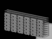
| 3D Composite Phase Change Natural Convection Heat Sink | 3D Composite Phase Change Track Heat Sink | 3D Composite Phase Change Heat Sink |
 |
 |
 |
| 3D composite phase change natural convection technology is applied to this heat sink. Under the condition of natural convection, its shell surface temperature is lower by about 12 ~ 14 ℃ compared to traditional heat sinks. Besides, its volume is 2/5 of the traditional ones with higher dustproof performance and IP degree. | This kind of heat sink is used in rail transportation, generator cooling high power heat sink, etc. 1. High heat dissipation capacity, Qmax > 7200 w 2. Low air volume, velocity and low noise design: Air flow rate < 1.0 m /s 3. The excellent properties of even temperature: Temperature difference of each point ΔT<3℃ 4. Heat source heat spreads to the entire surface of the heat sink rapidly. 5. The flow resistance can be effectively reduced. 6. The heat sink weight can be reduced by 30% ~ 50%. |
1. Overall size: 200 ~ 800x150 ~ 400(substrate size), Core body size :200 ~ 800x130 ~ 300x250 ~ 400mm 2. Cooling power: 3000 ~ 15000W 3. Contact R <0.010w/ ℃ 4. R heat sink: <5.0 ℃ 5. Substrate temperature difference: < 8.0 ℃ 6. Temperature rise of the eat sink: 25 ~ 38 ℃ 7. Pressure drop: < 150 ~ 260 pa 8. Heat sink volume reduced by 1/3 ~ 1/2. 9. Weight reduced by about 1/3 to 1/2. 10. Vertical (gravity direction) or horizontal use. |
 10Ah Battery pack (Common air cooling)
 -
 10Ah Battery pack (Heat pipe & air cooling)
 -
 10Ah Battery pack (Heat pipe & liquid cooling)
 -
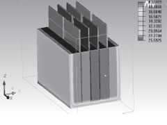
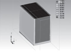 Aluminum battery enclosure Tmax=52.0℃
 -
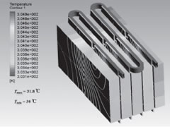
 Aluminum battery enclosure Tmax=43.0℃
 -
 Aluminum battery enclosure Tmax=31.8℃
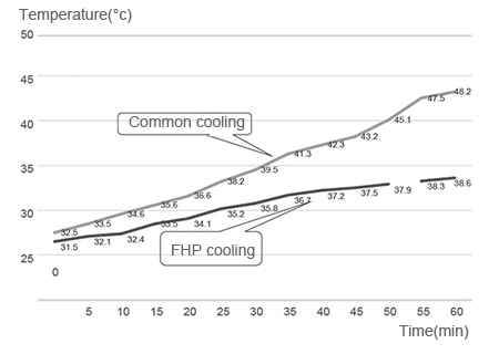 Battery discharging experiment (30℃ room temperature)
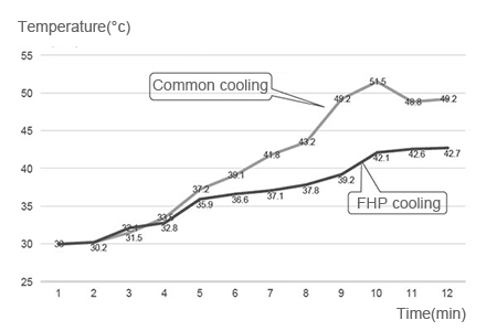
| Product series | Product picture | Overall dimensions (mm) | Thermal subsidence power (W) | Contact thermal resistance (W/k.m) | Heat sink thermal resistance(HP) (W/k.m) | Substrate temperature difference ( ℃ ) | Temperature rise of the heat sink ( ℃ ) | Fluid pressure drop (Pa) | Environment temperature ( ℃ ) | Direction of use ( ℃ ) |
Surface treatment | Fan selection | |
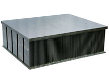
| 2D phase change heat sink | 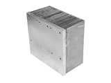 |
L(280) xW(240) xH(110) |
1500 ~ 2000 | 0.008 ~ 0.01 | 0.015 ~ 0.020 | 5 | 28 ~ 32 | 150 ~ 200 | -40 ~ 85 | Horizontal or vertical use and negative gravity use (performance attenuation 5 ~ 10%) | Anode, electrophoresis, electrochemical, paint, etc | 225 (EBM) Centrifugal fan | |
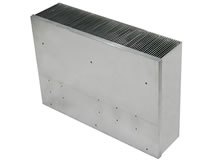
| 3D Phase Change Heat Sink | Natural convection heat dissipation |  |
L(550) xW(280) xH(140) |
125*5 | 0.05 | <0.01 | 5 | 41 ~ 46 | Natural convection | -40 ~ 50 | Vertical use | ||
| 3 IGBT (Econo) | 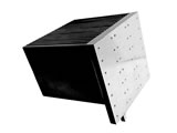 |
L(220 ~ 260) xW(220) xH(150 ~ 200) |
1500 ~ 2000 | <0.01 | <0.005 | 3 | 25 ~ 38 | <120 | -40 ~ 85 | Horizontal or vertical use (gravity direction) | 225 (EBM) Centrifugal fan | ||
| 6 IGBT (PrimePack) | 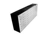 |
L(700) xW(290) xH(120) |
10200 ~ 12500 | <0.005 | <0.005 | 5 | 30 ~ 35 | <350 | -40 ~ 85 | ||||
| 6 IGBT (PrimePack) | 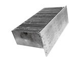 |
L(800) xW(350) xH(300 ~ 420) |
9000 ~ 13000 | <0.008 | <0.005 | 5 | 30 ~ 35 | <350 | -40 ~ 85 | 225 (EBM) Centrifugal fan | |||
| 12 IGBT (Econo) | 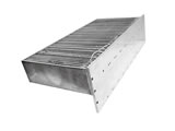 |
L(800 ~ 900) xW(300 ~ 400) xH(150 ~ 200) |
8000 ~ 11000 | <0.01 | <0.005 | 3 | 25 ~ 35 | <120 ~ 150 | -40 ~ 85 | 225 (EBM) Centrifugal fan, 250 axial flow fan or 400 (EBM) centrifugal fan | |||
| 9 IGBT (Econo) | 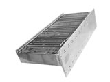 |
L(700 ~ 800) xW(300 ~ 400) xH(150 ~ 200) |
8000 ~ 11000 | <0.01 | <0.005 | 3 | 25 ~ 40 | <120 ~ 150 | -40 ~ 85 | ||||